ARGO E.M.C
1 - 604 - 436 - 0431
| |
ARGO E.M.C |
1 - 604 - 436 - 0431 |
NEW PRODUCT !!!
Field PROGRAMMABLE L.C.D P.I
Model: AG-PI-LCD64
|
CATEGORY ☞ Features |
|
[AG-PI-LCD64 User Manual : DOWN LOAD]
◎ Features
|
☆ Changeable & Programmable the floor P.I character on job site. ☆ Code input method : binary, gray and line/floor input by setting DIP s/w. ☆ Choose able character font and arrow symbols from 9 kind of it. ☆ 2 Wire MICRO COMM function for floor input code transfer to P.I unit. ☆ User-defined messages announcement play, and make able or disable. ☆ Adjustable time function by touch screen (Date, Hour & Minute). ☆ Live video (optional) and self testing. ☆ u-SD card socket for programming. ☆ Passing buzzer (selectable sound) and arrival gong control. ☆ Picture slideshow every each 4 floor stop. ☆ Easy to use function with mini toggle switches. ☆ Easy quick installation with 8 nuts fasten only. ☆ No bracket, only the LENS attach to COP. ☆ AG-PI-LCD64 is protected from EMInoise by system hardware. ☆ All functions are protected by system software and auto recovery function. Module dimensions : 7.94"W x 5.04"H x 1.56"D (Include LENS). ☆ 7 Inches wide viewing angle (800 x 480 pixels). ☆ 64K, 65536 colors and passive touch more than1 million. ☆ Lifetime: (Average) > 30,000 Hours. ☆ RTC timer and back up battery (CR1220) ☆ EN81-70 compliant. |
.[AG-PI-LCD64 User Manual : DOWN LOAD]
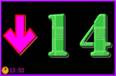
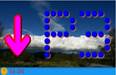
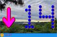
◎ Saved P.I character fonts
|
[ Font selecting with switches S0, S1, S2 and S3 ]
|
.[AG-PI-LCD64 User Manual : DOWN LOAD]
◎ Character programming with touch screen
|
|
Screen Meaning |
|
|
* #OF FLOOR * NOW * CHANGE * FLOOR ↑ * FLOOR ↓ * ERASE * ENTER
* BLANK * B/L * 0~9, A~Z * EXIT |
= Present number of floor or stop. =Current displaying P.I character. = New character to be change. = + 1 Floor toggle up. = - 1 Floor toggle down. = Remove the character in CHANGE. = The entered character in the CHANGE, it goes to NOW box. = Blank or empty character. = Not used. = Character for position indicator . = Exit from programming mode. |
|
.[AG-PI-LCD64 User Manual : DOWN LOAD]
Programming Example : Change P3 to M2 at 1st floor
|
Step 1) Set ‘ON’ Position of RP switch on PCB.
|
Step 2) Put ‘ON’ position of PW1 switch on PCB
|
|
Step 3) Shows ‘ 1 ’ floor in #of FLOOR box and currently P.I character ‘ P3 ’ in NOW box.
|
Step 4) Press number ‘ 2 ’, then number 2 shows at 1's position in the CHANGE box
|
|
Step 5) Press number ‘ M ’, then character M shows at 10's position in the CHANGE box .
|
Step 6) Press ‘ENTER’ then ‘M2’ character went to NOW box. First floor PI character changed and this data write to EEPROM.
|
|
Step 7) Press ‘EXIT’ then display this screen which is explain how to go back to normal run mode.
|
Need more programming ?
1) To change certain floor’s PI character,find there by pressing ‘FLOOR↑’ or ‘FLOOR↓’ and do same procedure from Step4 to Step6.
2) To correct a wrong character in CHANGE box then press ‘ERASE’ and re-enter right character or number. |
[AG-PI-LCD64 User Manual : DOWN LOAD]
◎ Setting time with touch screen
|
Step 1. Set ‘OFF’ Position of PW1 toggle switch. Step 2. Separate AG-PI-LCD64 module from C.O.P Step 3. Separate control part board from LENS. Step 4. Set ‘On’ Position of PW1 toggle switch. Step 5. Press the Step 6. The screen will be changed. (same as above picture) Step 7. Adjust hour or minute by press Step 8. Press Step 9. Set ‘OFF’ Position of PW1 toggle switch. Step 10. Re-assemble control part board to LENS. (became an AG-PI-LCD64 module) Step 11. Re-install AG-PI-LCD64 module on C O P. Step 12. Set ‘On’ Position of PW1 toggle switch. ( end ) |
|
..[AG-PI-LCD64 User Manual : DOWN LOAD]
|
|
.[AG-PI-LCD64 User Manual : DOWN LOAD]
◎ Wiring & System Functions
|
|
.[AG-PI-LCD64 User Manual : DOWN LOAD]
◎ Cut out & Studding Point DIM
|
|
..[AG-PI-LCD64 User Manual : DOWN LOAD]
![]()
Copyright (c) ARGO ELECTRONICS MICRO CONTROL LTD. All rights reserved.